Interfacing rotary encoders (repeated digital input) with your simulator
Rotary (incremental) encoders send a digital signal each time they are turned one increment/step to the left or right, which you can use as repeated inputs to quickly in- or decrease a value in your simulator using a turning knob (e.g. set the heading bug). I recommend you familiarize yourself with the general function and use of rotary encoders at least a bit before working with them. Here is how I installed them in my simulator:
 1) Get yourself an USB interface board. They are commonly referred to as joystick boards. As already stated in other tutorials, I find the boards from Leo Bodnar Electronics of very good quality and I use them in my simulator.
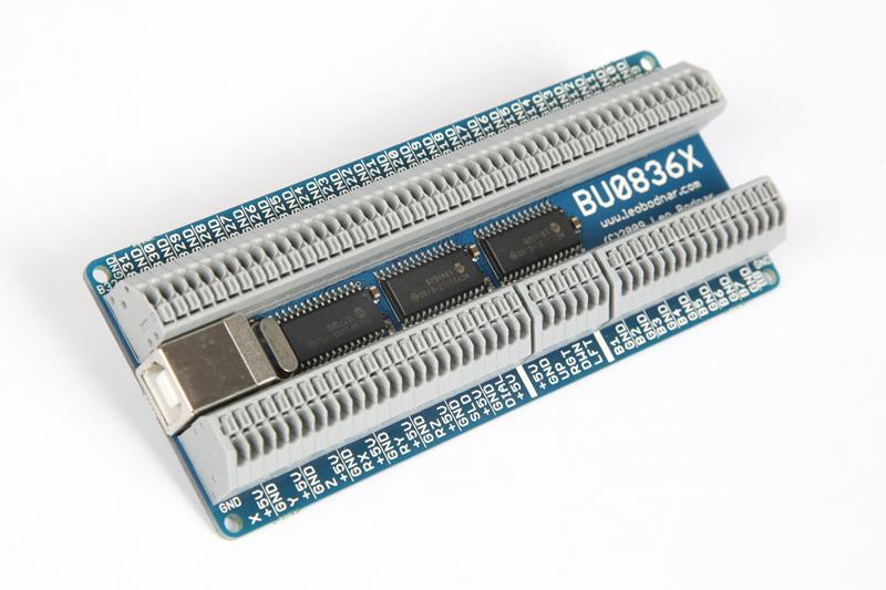
The board shown on the left is the Leo Bodnar BU0836X 12-Bit Joystick Board. You can wire 32 digital inputs (e.g. buttons) to it, but an encoder requires two inputs, so this leaves you with a maximum of 16 encoders per board. If you don’t require that much encoding, you can also connect a mix of buttons, potentiometers and encoders together on one board.
 2) Then you need encoders. Look for good quality, 360° continuous travel, (about) 16-20 detents per revolution (with 1 pulse per detent) type rotary (incremental) encoders. And of course make sure they match the physical dimensions (e.g. shaft diameter and length) for your favored knobs. Some encoders feature a momentary push button function. This connects to an additional input terminal on the board and can be very useful, e.g. on the altimeter (Kollsman) knob to switch between QNH and standard.
3) Connect the encoders to the board. Most encoders have 3 (or 4) connectors: GND, CW rotation and CCW rotation (and sometimes V+ / 5V). CW and CCW connectors are sometimes labelled CLK (clock) and DT (data), S1 and S2, or simply A and B, the function remains the same. When using the Leo Bodnar board, always use an odd numbered input terminal for the first input and the adjacent one for the second, e.g. 1-2, 3-4. This is important for the encoder software which I’ll describe shortly.
Encoders with a push button will have one additional connector labelled SW (switch), KEY or similar. Connect it to an empty button input on the board if you want to use it.
CAUTION: Always disconnect the board while working on it!
 4) Run the Encoder Configuration Software: Encoders will not, unfortunately, just output pulses on the CW or CCW terminals corresponding to the direction of rotation. Instead, they generate something called a 2-bit Quadrature Code, also referred to as
Grey Code
(see here for more info). This is a set of pulses, which enables the receiving board or software to determine the direction and speed of rotation.
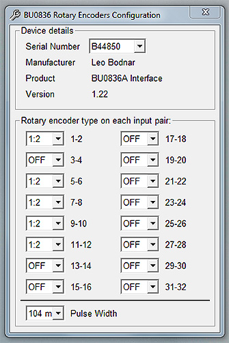
Luckily, Leo Bodnar board users don’t have to worry about that and can just run their Encoder Configuration Software available here.
Selecting the encoder type (pulse per detent) on the listed input terminals will tell the board to interpret input on these terminals as encoder code.
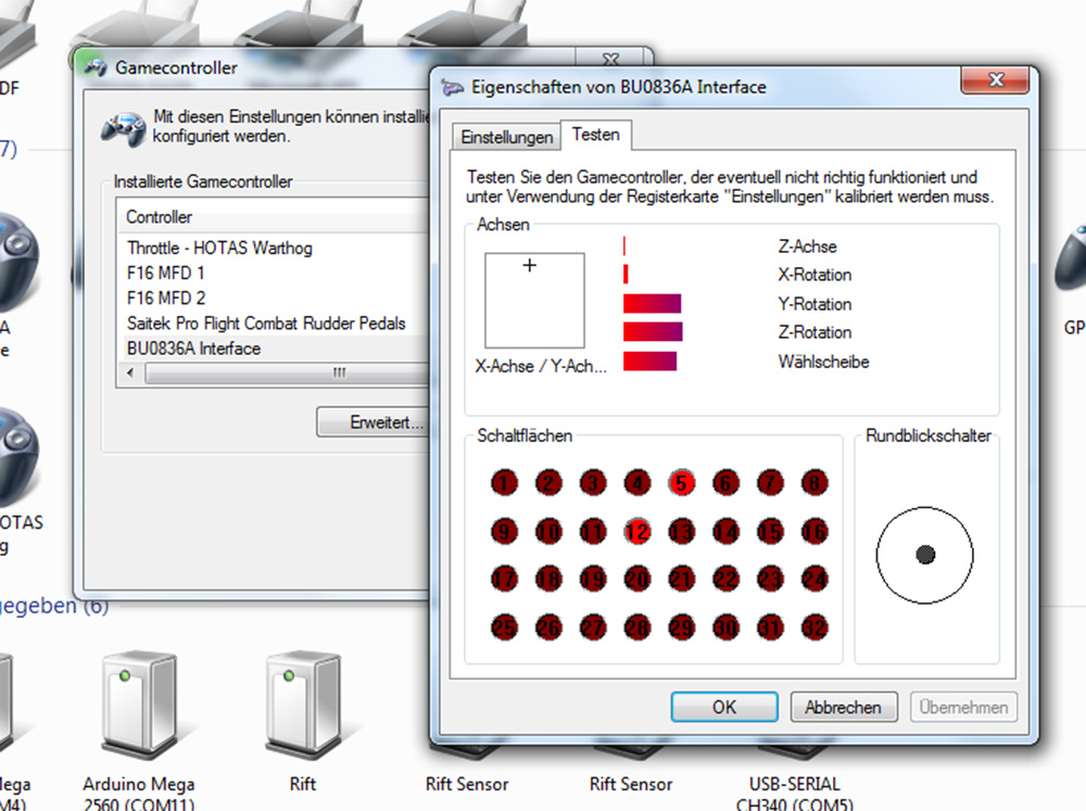
 5) (Re)Connect the board to your computer and open the Gamecontroller dialog. If you wired everything the right way and configured the Encoder Software correctly, rotating your encoder the one way or the other should now show up as repeated button presses which you can assign in your simulator.
Sorry, no posts here yet... go ahead and be the first ;)